
After the positive reception of my initial post on recursive RTL, which sparked numerous insightful discussions, I’m excited to present Part 2. In this installment, I’ll delve into addressing common misunderstandings while also introducing an optimization technique for the adder tree discussed previously.
Why not create an adder tree through iterative accumulation?
This question emerged as one of the most frequent inquiries following the publication of my initial post. If you found yourself asking the same question, rest assured, you’re not alone. It’s a natural inclination to approach the accumulation of an input array through iteration, a method commonly employed in virtually any non-RTL language for adding array elements.
The answer to this question isn’t straightforward or immediately evident, but the confusion from which it originates is explained in my inaugural StittHub post: Design the Circuit, then Write the Code. When you’re coding a conventional accumulation loop, you’re likely solely focusing on the circuit’s behavior without considering how that behavior should be implemented as a circuit. You know you want to add all the numbers in an array, but you haven’t considered how the circuit should accomplish that task. Perhaps you’ve adopted the mindset that you’re intentionally leaving it up to the synthesis tool to determine the optimal method for performing the accumulation. However, in general, that approach is inadvisable because unless you’re working with pure combinational logic, synthesis optimizations are heavily restricted by the way you write your code.
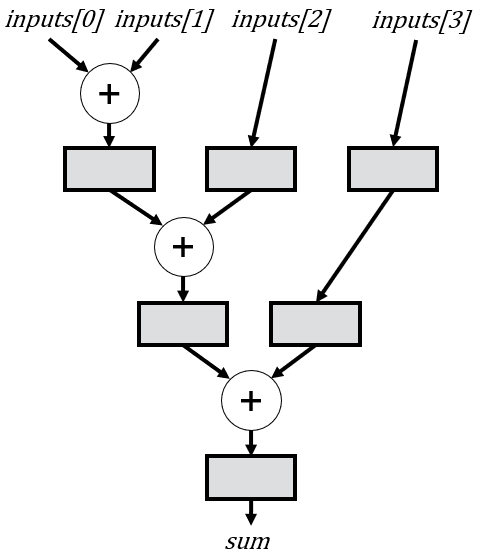
The short answer to why you shouldn’t implement an adder tree with an accumulation loop is simply because it won’t synthesize to an adder tree without significant modifications. Instead, as I always emphasize, you should design your circuit first, which in this case means deciding exactly how the circuit should perform the additions. The balanced adder tree schematic represents my design for achieving the behavior of summing all the numbers in an array.
An iterative accumulation isn’t necessarily bad, but it probably isn’t what you want in most situations. Let’s take a more detailed look at why.
Iterative Accumulation: Attempt 1
If someone inexperienced with RTL attempted to add an array of numbers, they might opt for a solution like this:
module add_tree1 #(
    parameter int NUM_INPUTS  = 4,
    parameter int INPUT_WIDTH = 16
) (
    input  logic                                      clk,
    input  logic                                      rst,
    input  logic                                      en,
    input  logic [                   INPUT_WIDTH-1:0] inputs[NUM_INPUTS],
    output logic [INPUT_WIDTH+$clog2(NUM_INPUTS)-1:0] sum
);

    always_ff @(posedge clk or posedge rst) begin
        if (rst) sum <= '0;
        else if (en) begin
            sum <= 0;
            for (int i = 0; i < NUM_INPUTS; i++) begin
                sum <= sum + inputs[i];
            end
        end
    end
endmodule
On the surface, this code seems right, but here is what it synthesizes into:
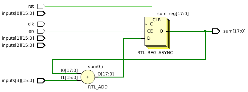
There is only one adder! How can it possibly add four inputs with one adder? It simply can’t. This circuit will not work.
The problem with this code stems from a misunderstanding of how non-blocking assignments function. Non-blocking assignments defer the update of a signal’s value until the end of the time step. Therefore, any read from the same signal within the time step yields the previous value.
The non-blocking timing mechanism leads to each addition utilizing the initial value of sum at the start of every time step. Consequently, throughout each iteration of the loop, sum retains a constant value, rendering the iteration futile. As a result, only the final assignment to sum has any effect, mirroring precisely what we observe in the schematic.
If the timing nuances of non-blocking signals confuse you, don’t worry. It isn’t the primary focus of this article, and I plan to delve deeper into it in future posts. I’m addressing it here solely because it’s a question that many have asked regarding why this approach wouldn’t function as expected in other languages.
Iterative Accumulation: Attempt 2
In an attempt to fix the issue with the previous attempt, an inexperienced RTL designer might try changing the non-blocking assignments to blocking assignments. For example:
module add_tree2 #(
    parameter int NUM_INPUTS  = 4,
    parameter int INPUT_WIDTH = 16
) (
    input  logic                                      clk,
    input  logic                                      rst,
    input  logic                                      en,
    input  logic [                   INPUT_WIDTH-1:0] inputs[NUM_INPUTS],
    output logic [INPUT_WIDTH+$clog2(NUM_INPUTS)-1:0] sum
);
    always @(posedge clk or posedge rst) begin
        if (rst) sum = '0;
        else if (en) begin
            sum = 0;
            for (int i = 0; i < NUM_INPUTS; i++) begin
                sum = sum + inputs[i];
            end
        end
    end
endmodule
The resulting schematic looks like this:
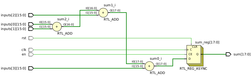
This schematic appears improved, but it still has problems. Primarily, it doesn’t implement a tree; rather, it represents a sequence of adders, as dictated by the code. While a linear sequence might be considered a degenerate form of a tree, it deviates from the type of tree structure we aim to achieve.
A significant potential issue with this code is the absence of registers between the adders. While this might be tolerable for a small number of inputs, if we were to increase NUM_INPUTS to 128, the logic delay through 127 adders would significantly restrict the clock frequency.
Lastly, it’s worth noting that the code employs the risky practice of using blocking assignments on a clock edge. Although I don’t outright prohibit such a practice, it’s crucial to avoid writing code in this manner unless you possess a thorough understanding of its implications on synthesis.
Iterative Accumulation: Attempt 3
Let’s attempt to address the issue of missing registers between the adders. One potential solution could be implemented as follows:
module add_tree3 #(
    parameter int NUM_INPUTS  = 4,
    parameter int INPUT_WIDTH = 16
) (
    input  logic                                      clk,
    input  logic                                      rst,
    input  logic                                      en,
    input  logic [                   INPUT_WIDTH-1:0] inputs[NUM_INPUTS],
    output logic [INPUT_WIDTH+$clog2(NUM_INPUTS)-1:0] sum
);
    logic [INPUT_WIDTH-1:0] add_r[NUM_INPUTS-1];

    always_ff @(posedge clk or posedge rst) begin
        if (rst) begin
            add_r <= '{default: '0};
        end else if (en) begin
            add_r[0] <= inputs[0] + inputs[1];

            for (int i = 1; i < NUM_INPUTS - 1; i++) begin
                add_r[i] <= inputs[i+1] + add_r[i-1];
            end
        end
    end

    assign sum = add_r[NUM_INPUTS-2];
endmodule
In this code, we explicitly introduce registers. If you haven’t yet explored my tutorials on SystemVerilog and/or VHDL, there’s a straightforward rule regarding registers: if you assign a signal on a rising clock edge using a non-blocking assignment, it will be synthesized as a register. A quick side note related to this and the previous example: blocking assignments (or variable assignments in VHDL) have more intricate rules, which I’ll delve into in another article.
If we look at the resulting schematic, we’ve solved our register problem:
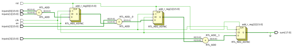
However, we still have a few remaining problems to solve. Firstly, the structure still doesn’t adhere to the tree architecture we aimed for. More critically, there are two distinct incorrect behaviors present here. Upon closer inspection, you’ll observe that the output of every adder is fixed at 16 bits. Consequently, we aren’t preserving all the necessary bits required to handle overflow. Instead, the surplus bits in the output are simply tied to ground.
Second, there is an ever bigger problem here. This circuit isn’t capable of adding NUM_INPUTS inputs every cycle; instead, it requires executing the adds across NUM_INPUTS-1 cycles. If we change inputs[2] in the first cycle, or inputs[3] in the first or second cycle, we won’t be adding all the original inputs. If that behavior is what you want, then this implementation is fine. However, our initial intent was to facilitate the addition of NUM_INPUTS new inputs every cycle.
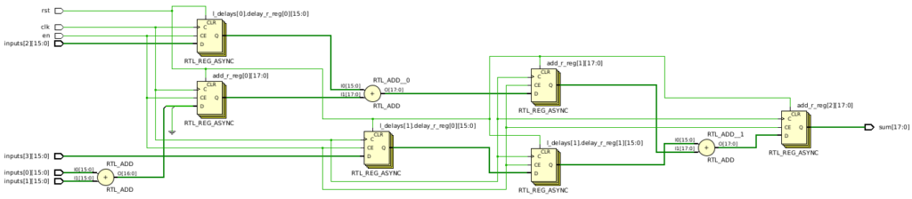
To accomplish that goal, we need to delay inputs[2] by one cycle and inputs[3] by two cycles:
Iterative Accumulation: Attempt 4
In this updated version of the code, we expand upon our previous implementation to add the extra bits to preserve overflow, and to incorporate the appropriate number of delay registers, mirroring the schematic provided above. While straightforward for a single NUM_INPUTS value, ensuring compatibility with any number of inputs requires a bit more thought. Thankfully, there’s a simple pattern we can leverage. Firstly, we require NUM_INPUTS-2 separate delays, as the first two inputs necessitate no delay. Secondly, the delay length for a given input i is i-1. For instance, inputs[2] undergoes a delay of 1 cycle, inputs[3] a delay of two cycles, inputs[4] a delay of three cycles, etc.
In the code below, we add a generate loop that creates each individual delay. While we could instantiate a separate delay module in the loop, I opted to keep this example self-contained.
// Greg Stitt
// StittHub (www.stitt-hub.com)

module add_tree4 #(
    parameter int NUM_INPUTS  = 4,
    parameter int INPUT_WIDTH = 16
) (
    input  logic                                      clk,
    input  logic                                      rst,
    input  logic                                      en,
    input  logic [                   INPUT_WIDTH-1:0] inputs[NUM_INPUTS],
    output logic [INPUT_WIDTH+$clog2(NUM_INPUTS)-1:0] sum
);

    logic [INPUT_WIDTH-1:0] inputs_aligned[NUM_INPUTS];

    // The first two inputs don't require delays.
    assign inputs_aligned[0] = inputs[0];
    assign inputs_aligned[1] = inputs[1];

    // Create NUM_INPUTS-2 delays, where each delay is
    // 1 cycle longer than the previous one.
    for (genvar ii = 0; ii < NUM_INPUTS - 2; ii++) begin : l_delays

        logic [INPUT_WIDTH-1:0] delay_r[ii+1];

        always_ff @(posedge clk or posedge rst) begin
            if (rst) delay_r <= '{default: '0};
            else if (en) begin
                delay_r[0] <= inputs[ii+2];
                for (int i = 1; i < ii + 1; i++) begin
                    delay_r[i] <= delay_r[i-1];
                end
            end
        end

        assign inputs_aligned[ii+2] = delay_r[ii];
    end

    // The same adder code from before, but using inputs_aligned.
    logic [INPUT_WIDTH+$clog2(NUM_INPUTS)-1:0] add_r[NUM_INPUTS-1];

    always_ff @(posedge clk or posedge rst) begin
        if (rst) begin
            add_r <= '{default: '0};
        end else if (en) begin
            add_r[0] <= inputs_aligned[0] + inputs_aligned[1];

            for (int i = 1; i < NUM_INPUTS - 1; i++) begin
                add_r[i] <= inputs_aligned[i+1] + add_r[i-1];
            end
        end
    end

    assign sum = add_r[NUM_INPUTS-2];
endmodule
If we synthesize this, we now have the correct delays to be able to take NUM_INPUTS new inputs every cycle:
However, an issue persists: we still lack the desired tree structure. Instead, we’re still dealing with a linear sequence of adders, leading to increased latency and unnecessary delays. While this might not seem significant for a small-scale example, the implications become clear when considering NUM_INPUTS=128. The linear sequence would require 126 separate delays, with delay lengths ranging from 1 cycle to 125 cycles. This results in a staggering total of 7,875 delay registers, in addition to 127 more registers for all the adders. Furthermore, the linear sequence incurs a latency of 127 cycles. By contrast, the adder tree from the previous article boasts a latency of just 7 cycles and requires a total of 127 registers. Clearly, the adder tree is the superior solution.
We could attempt to transform the iterative code into a tree structure by creating an array with an element for each node of the tree. Each node would be assigned an index (e.g., the two children of node i are stored at 2i+1 and 2i+2). While this approach might be relatively straightforward for a power-of-2 number of inputs, I challenge anyone to try it for any NUM_INPUTS value. It’s not impossible, but I can almost guarantee that during the coding process, you’ll find it easier to concede and accept that the recursive implementation is far simpler while achieving the same result.
Alternatively, if compelled to pursue an iterative implementation, I would design the module to require a power-of-2 number of inputs. Then, if I needed to add a size that wasn’t a power-of-2, I would extend the actual tree size to the next higher power-of-2, connecting the unneeded inputs to 0, and rely on synthesis to optimize away the unused adders and registers. Or, I could simply opt for the recursive code and sidestep that complication entirely. Essentially, there’s no scenario where I would opt for an iterative approach in this example.
Recursive Adder Tree Part 2: Optimizing Delays
Now that I hope you see the value in the recursive adder tree, let’s revisit the previous recursive code from the original article. That code employed the following recursive rule, which divided a tree into equal-sized subtrees for even input amounts or nearly equal-sized subtrees for odd input amounts:
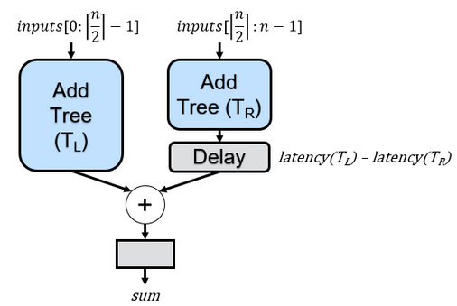
The logic behind this splitting strategy was based on the fact that the greater the difference in depth between the two subtrees, the more delay would be required to align their outputs. While this logic holds merit, it’s not necessarily the optimal solution. Consider the following example where n (i.e., NUM_INPUTS) = 5:
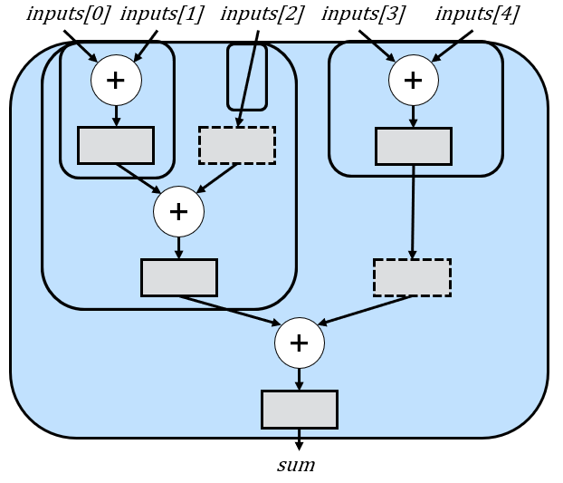
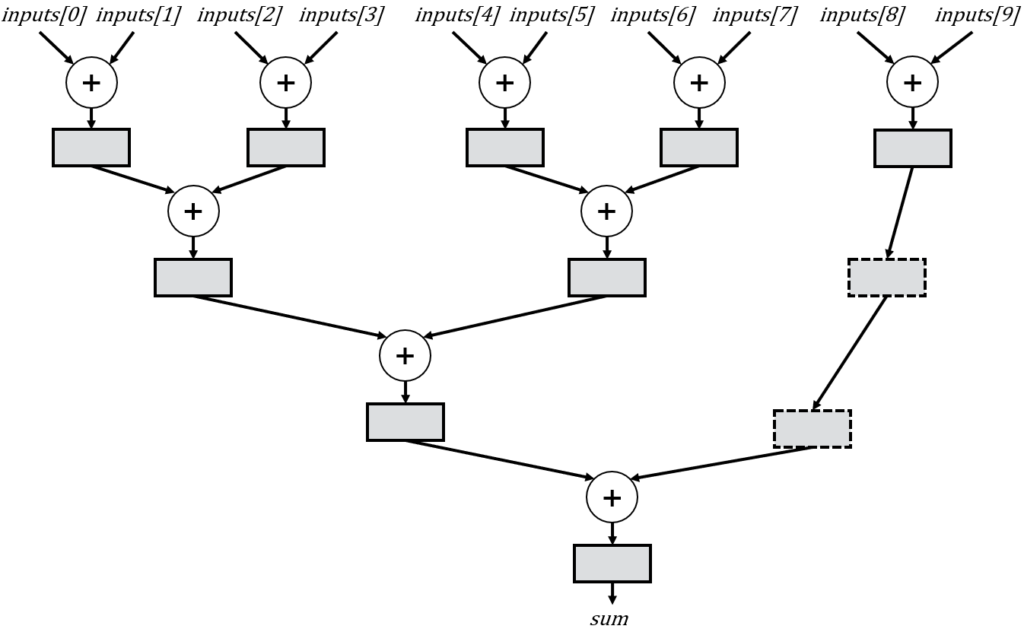
In this case, the splitting strategy does in fact find the optimal amount of delays, which are shown as dashed rectangles. However, let’s now look at n = 10:
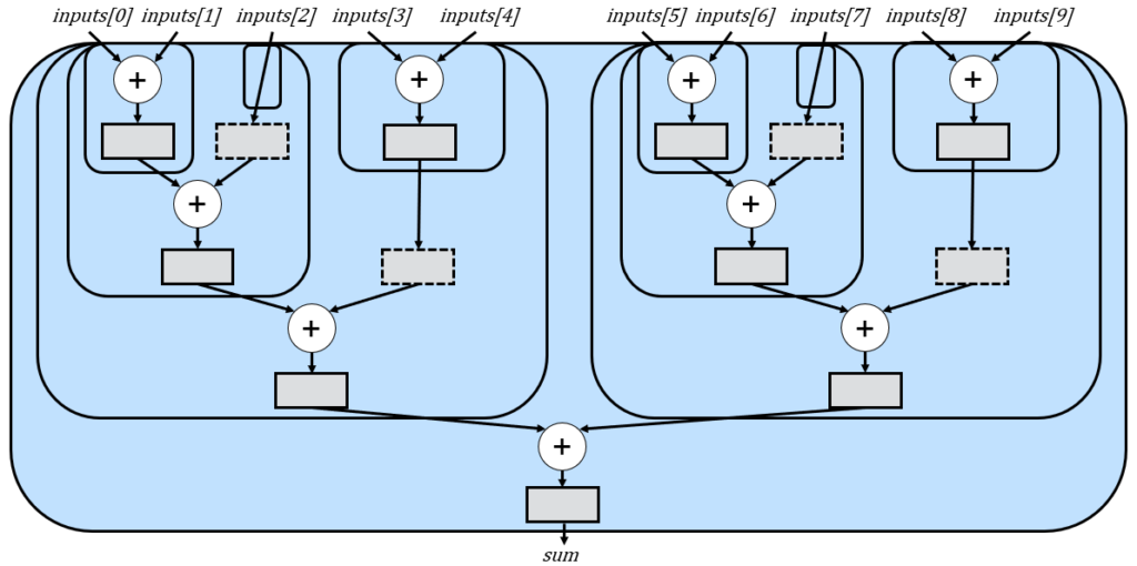
This version simply replicates the n=5 version and then adds both subtrees. This exposes an optimization opportunity. Notice that the delays we made for n=5 are now also replicated unnecessary. If we had used a different splitting strategy, we could have reduced the number of delays from 4 to 2. For example:
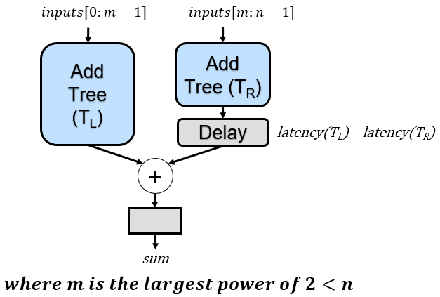
To construct this improved tree, we must adjust our previous recursive rule. Once more, we split the tree into two subtrees at each step. However, the first subtree will now utilize a number of inputs that represents the largest power of 2 less than the total number of tree inputs. The remaining inputs are then simply assigned to the second subtree
When applied to n=10, we achieve the desired circuit, with recursive calls illustrated below, accompanied by dashed rectangles representing the reduced delay registers:
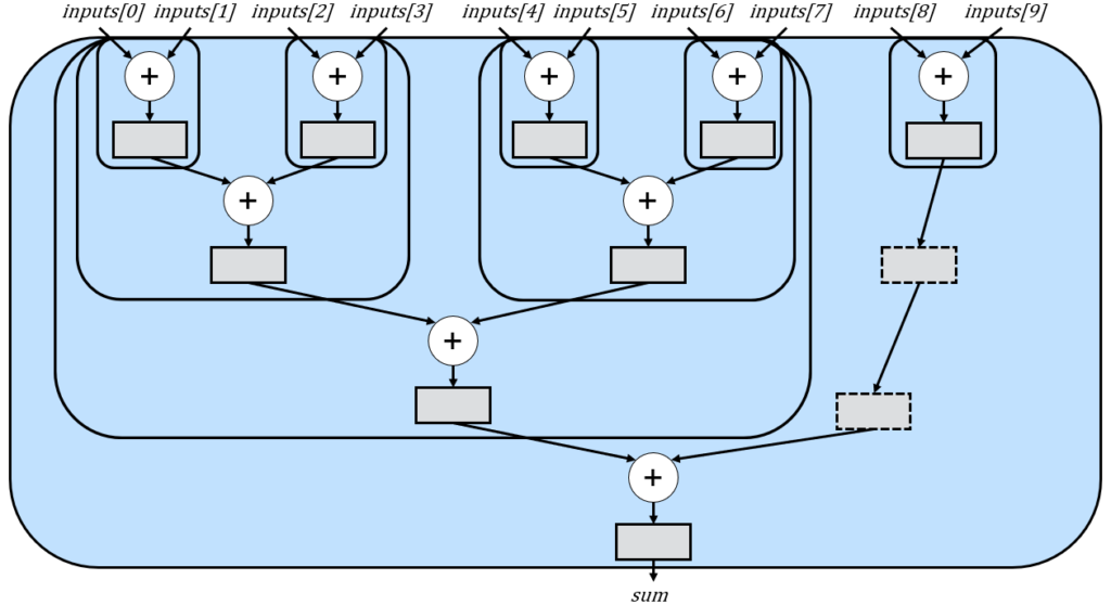
Essentially, the tree for n=10 is initially divided into a tree with 8 inputs (the largest power of 2 less than 10) and a tree with 10-8=2 inputs, while adding two cycles of delay to account for the differences in subtree heights.
Upon first thought, it is not obvious why this approach is better than the equal-sized subtree strategy. After all, the power-of-2 strategy deliberately increases the difference in depth between the two subtrees.
The effectiveness of this splitting strategy lies in the fact that a tree with a power-of-2 number of inputs necessitates no delays for alignment. Consequently, we’re essentially minimizing the need for delays within the subtrees as much as possible. While this approach does increase the delays required to align the two subtrees, it eliminates the redundant delays observed in the earlier splitting strategy.
As an added bonus, the delays are now adjacent to each other, which opens up additional optimization possibilities. Long delays can potentially be replaced by specialized resources, such as Shift Register LUTs (SRLs) on Xilinx/AMD FPGAs, Memory LABs (MLABs) on Intel/Altera devices, or on-chip RAM resources on any FPGA or ASIC.
The updated code is shown below. One significant advantage of recursion for this example is the ability to make substantial changes to the circuit structure by modifying just two lines of code. First, we calculate the largest power of two that is less than NUM_INPUTS and assign it as the number of inputs in the left subtree:
// Determine the number of inputs for the left tree. This calculates
// the largest power of 2 that is less than NUM_INPUTS.
localparam int LEFT_TREE_INPUTS = int'(2**($clog2(NUM_INPUTS)-1));
Next, we calculate the number of inputs for the right subtree, which comprises the remaining inputs.
// The number of inputs to the right subtree is the remaining amount.
localparam int RIGHT_TREE_INPUTS = NUM_INPUTS - LEFT_TREE_INPUTS;
Every other line of code remains unchanged, resulting in our final optimized solution:
// Greg Stitt, Christopher Crary
// StittHub (stitt-hub.com)

module add_tree
#(
    parameter int NUM_INPUTS=8,
    parameter int INPUT_WIDTH=16
) (
    input  logic                                      clk,
    input  logic                                      rst,
    input  logic                                      en,
    input  logic [                   INPUT_WIDTH-1:0] inputs[NUM_INPUTS],
    output logic [INPUT_WIDTH+$clog2(NUM_INPUTS)-1:0] sum
);
    generate
        if (INPUT_WIDTH < 1) begin : l_width_validation
            $fatal(1, "ERROR: INPUT_WIDTH must be positive.");
        end

        if (NUM_INPUTS < 1) begin : l_num_inputs_validation
            $fatal(1, "ERROR: Number of inputs must be positive.");
        end else if (NUM_INPUTS == 1) begin : l_base_1_input
            assign sum = inputs[0];
        end else begin : l_recurse

            //--------------------------------------------------------------------
            // Create the left subtree
            //--------------------------------------------------------------------
            localparam int LEFT_TREE_INPUTS = int'(2**($clog2(NUM_INPUTS)-1));
            localparam int LEFT_TREE_DEPTH = $clog2(LEFT_TREE_INPUTS);
            logic [INPUT_WIDTH + $clog2(LEFT_TREE_INPUTS)-1:0] left_sum;

            add_tree #(
                .NUM_INPUTS (LEFT_TREE_INPUTS),
                .INPUT_WIDTH(INPUT_WIDTH)
            ) left_tree (
                .clk   (clk),
                .rst   (rst),
                .en    (en),
                .inputs(inputs[0+:LEFT_TREE_INPUTS]),
                .sum   (left_sum)
            );

            //--------------------------------------------------------------------
            // Create the right subtree.
            //--------------------------------------------------------------------
            localparam int RIGHT_TREE_INPUTS = NUM_INPUTS - LEFT_TREE_INPUTS;
            localparam int RIGHT_TREE_DEPTH = $clog2(RIGHT_TREE_INPUTS);
            logic [INPUT_WIDTH + $clog2(RIGHT_TREE_INPUTS)-1:0] right_sum, right_sum_unaligned;

            add_tree #(
                .NUM_INPUTS (RIGHT_TREE_INPUTS),
                .INPUT_WIDTH(INPUT_WIDTH)
            ) right_tree (
                .clk   (clk),
                .rst   (rst),
                .en    (en),
                .inputs(inputs[LEFT_TREE_INPUTS+:RIGHT_TREE_INPUTS]),
                .sum   (right_sum_unaligned)
            );

            //--------------------------------------------------------------------
            // Delay the right sum so it is aligned with the left sum.
            //--------------------------------------------------------------------
            localparam int LATENCY_DIFFERENCE = LEFT_TREE_DEPTH - RIGHT_TREE_DEPTH;

            if (LATENCY_DIFFERENCE > 0) begin : l_delay
                logic [$bits(right_sum)-1:0] delay_r[LATENCY_DIFFERENCE];

                always_ff @(posedge clk or posedge rst) begin
                    if (rst) delay_r <= '{default: '0};
                    else if (en) begin
                        delay_r[0] <= right_sum_unaligned;
                        for (int i = 1; i < LATENCY_DIFFERENCE; i++) begin
                            delay_r[i] <= delay_r[i-1];
                        end
                    end
                end

                assign right_sum = delay_r[LATENCY_DIFFERENCE-1];
            end else begin : l_no_delay
                assign right_sum = right_sum_unaligned;
            end

            // Add the two trees together.
            always_ff @(posedge clk or posedge rst) begin
                if (rst) sum <= '0;
                else if (en) sum <= left_sum + right_sum;
            end
        end
    endgenerate
endmodule
Additional Examples
There are still numerous insights about recursion that I haven’t yet shared. I encourage you to explore my papers, examine where else I’ve implemented recursion, and consider situations where you might employ it. Recently, I presented a paper at the 2024 ACM/SIGDA International Symposium on Field-Programmable Gate Arrays (FPGA), which introduced an architecture for low-latency line-rate parsing of variable-length fields on SmartNICs. Much of that design relied on recursion, including a priority encoder, which is extensively explained in the paper. I completed that code in at most two weeks. Had I attempted an iterative approach, I’d likely still be grappling with it.