
Despite reset logic not being the most exciting topic, I’ve been excited to write this article for some time, especially since this is one of the topics I never managed to fit into my lectures at UF.
I’m excited because this post will shed light on the fact that there are widespread RTL coding styles for resets that synthesize unnecessary logic and slow down your clock. There’s a good chance you’ve accidentally done this before and never noticed. I likely have a few examples in my tutorials where I still make the same mistake. It’s easy to overlook, especially in a large design. As Olof Kindgren said in his similar article on this topic: “you are probably doing your reset wrong in your RTL code.”
What’s the problem?
Let’s first take a look at the following example:
module pipeline1 #(
    parameter int DATA_WIDTH = 16
) (
    input  logic                  clk,
    input  logic                  rst,
    input  logic                  valid_in,
    input  logic [DATA_WIDTH-1:0] inputs   [8],
    output logic                  valid_out,
    output logic [DATA_WIDTH-1:0] sum
);

    logic [DATA_WIDTH-1:0] add0_r, add1_r, add2_r;
    logic [1:0] valid_r;

    always_ff @(posedge clk) begin
        if (rst) begin
            valid_r <= '0;
            add0_r  <= '0;  // Doesn't need to be reset
            add1_r  <= '0;  // Doesn't need to be reset
            add2_r  <= '0;  // Doesn't need to be reset
        end else begin
            valid_r[0] <= valid_in;
            valid_r[1] <= valid_r[0];

            add0_r <= inputs[0] + inputs[1];
            add1_r <= inputs[2] + inputs[3];
            add2_r <= add0_r + add1_r;
        end
    end

    assign valid_out = valid_r[1];
    assign sum = add2_r;

endmodule
This SystemVerilog example synthesizes to the following small pipeline, which is exactly what we would expect:
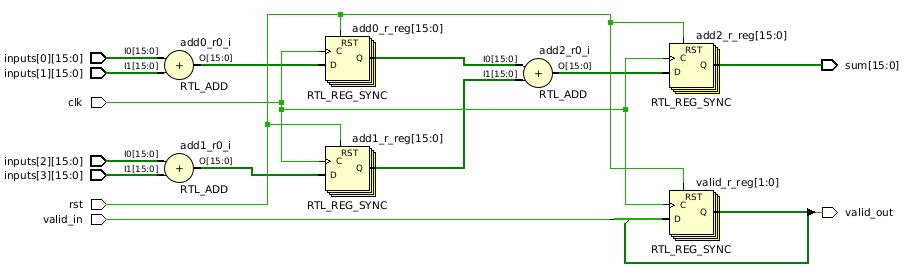
There’s nothing incorrect about this design, but it leaves room for optimization. With most pipelines, you only need to reset the logic that specifies when the output is valid. Resetting everything doesn’t affect correctness, but for a large design, resetting all the registers creates massive fan-out on the reset signal, which will reduce clock frequencies due to worse placement and routing results.
A common timing optimization (explained in more detail on my timing optimization tutorial) is to only reset signals that are needed for correct functionality. In this example, only the logic for valid_out needs to be reset. As long as valid_out is 0, outside circuits should ignore the sum output. To implement this optimization, many people would change the code in the following way:
module pipeline2 #(
    parameter int DATA_WIDTH = 16
) (
    input  logic                  clk,
    input  logic                  rst,
    input  logic                  valid_in,
    input  logic [DATA_WIDTH-1:0] inputs   [4],
    output logic                  valid_out,
    output logic [DATA_WIDTH-1:0] sum
);

    logic [DATA_WIDTH-1:0] add0_r, add1_r, add2_r;
    logic [1:0] valid_r;

    always_ff @(posedge clk) begin
        if (rst) begin
            valid_r <= '0; // ONLY RESET VALID LOGIC
        end else begin
            valid_r[0] <= valid_in;
            valid_r[1] <= valid_r[0];

            add0_r <= inputs[0] + inputs[1];
            add1_r <= inputs[2] + inputs[3];
            add2_r <= add0_r + add1_r;
        end
    end

    assign valid_out = valid_r[1];
    assign sum = add2_r;

endmodule
This appears to be an effective optimization strategy. However, when we synthesize the code, we now see the following:
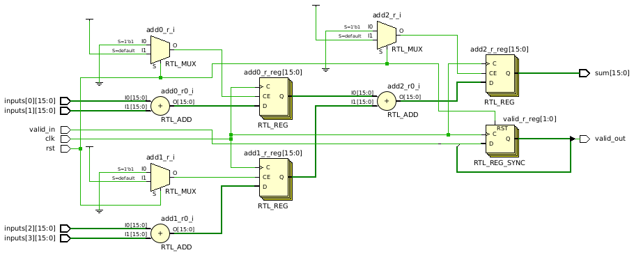
Our pipeline now has a few muxes! Why would not resetting certain signals create extra muxes? We would certainly never design a circuit this way, so we don’t want synthesis adding this extra logic. In the best case, these muxes get absorbed into unused resources, but we certainly don’t want to rely on that.
Although confusing, it starts to make sense when you consider what is supposed to happen during reset. You are probably telling yourself “I don’t care what happens on reset for the signals that don’t get reset,” which is perfectly fine. However, that behavior is not what is specified by this code.
The semantics of this code specify that any signal not assigned during reset needs to preserve its current value. While that behavior provides correct functionality, the synthesis tool needs to add extra logic to achieve this behavior. One possible way that synthesis could achieve this behavior is by adding a mux in front of the adder registers. This mux would then simply recirculate the register output while the reset is asserted. Clearly, this mux is not wanted since it is a pretty significant increase in area due to the adder registers having 16 bits in this example.
Fortunately, what we’re seeing isn’t quite that bad, but it’s still not good. Notice that the flip-flops now have a CE input, which is an enable signal. The mux uses the reset as a select to either enable or disable the register. Basically, this mux is acting like an inverter, so in a different synthesis tool, you might see an inverter instead. Side note: if you’re wondering why the Vivado synthesis tool uses a mux here for an inverter, I doubt anyone outside of AMD/Xilinx knows. You’ll find these small quirks in all synthesis tools.
If we change the reset to active low and resynthesize, the muxes disappear from the adder registers because we no longer need to invert the reset signal before connecting it to the register enable:
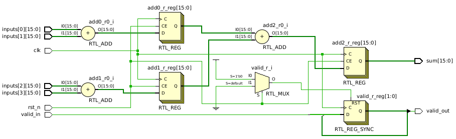
You might think this gets rid of the problem, but it just changes it. The active-low reset eliminates the inverter/mux from the adder registers, but it still has the same fan-out problem that we were trying to avoid. Notice the reset signal still fans out to every register, which is what we were originally trying to optimize!
You might also notice a new mux/inverter on the the valid register. That mux is due to this particular FPGA having flip-flops with an active high reset, which is unrelated to the reset problem we are focusing on. Vivado is simply inverting the active-low reset here to work with the FPGA’s flip-flops.
How do we avoid this extra logic when we don’t want to reset all registers? The rest of the article describes three potential solutions.
Solution 1: Use don’t cares
Earlier we talked about how we didn’t care what happened to the value of the non-reset registers while the reset was asserted. We can actually code that exact specification by explicitly using don’t care values during reset:
module pipeline3 #(
    parameter int DATA_WIDTH = 16
) (
    input  logic                  clk,
    input  logic                  rst,
    input  logic                  valid_in,
    input  logic [DATA_WIDTH-1:0] inputs   [4],
    output logic                  valid_out,
    output logic [DATA_WIDTH-1:0] sum
);

    logic [DATA_WIDTH-1:0] add0_r, add1_r, add2_r;
    logic [1:0] valid_r;

    always_ff @(posedge clk) begin
        if (rst) begin
            valid_r <= '0;
            add0_r  <= 'X;
            add1_r  <= 'X;
            add2_r  <= 'X;
        end else begin
            valid_r[0] <= valid_in;
            valid_r[1] <= valid_r[0];

            add0_r <= inputs[0] + inputs[1];
            add1_r <= inputs[2] + inputs[3];
            add2_r <= add0_r + add1_r;
        end
    end

    assign valid_out = valid_r[1];
    assign sum = add2_r;

endmodule
If we synthesize this, we get the exact circuit we wanted, without any muxes or inverters, and with no reset being connected to the adder registers:
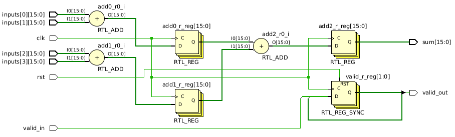
Although this solution can work, I prefer other solutions. The don’t cares provide a convenient fix, but there is no guarantee that synthesis will disconnect the reset from the adder registers. Our code tells the synthesis tool we don’t care what it does, which is pretty vague. Fortunately, most tools do what we want, but synthesis could leave reset connected and set the flip-flops to 0 or 1 on reset. If you know your tool will do what you want, you can use this, but I prefer to write code that I know will synthesize to what I want in any tool.
Solution 2: Move the reset if statement
For various reasons, many designers (myself included) tend to specify reset logic first in a clocked process. My best guess as to why is that synthesis tools often provide a template to follow for certain types of logic, and those templates have historically specified reset first for sequential logic.
Despite the common practice, there is no technical reason why we can’t move the reset logic. For example:
module pipeline4 #(
    parameter int DATA_WIDTH = 16
) (
    input  logic                  clk,
    input  logic                  rst,
    input  logic                  valid_in,
    input  logic [DATA_WIDTH-1:0] inputs   [4],
    output logic                  valid_out,
    output logic [DATA_WIDTH-1:0] sum
);

    logic [DATA_WIDTH-1:0] add0_r, add1_r, add2_r;
    logic [1:0] valid_r;

    always_ff @(posedge clk) begin
        valid_r[0] <= valid_in;
        valid_r[1] <= valid_r[0];

        add0_r <= inputs[0] + inputs[1];
        add1_r <= inputs[2] + inputs[3];
        add2_r <= add0_r + add1_r;

        if (rst) begin
            valid_r <= '0;
        end
    end

    assign valid_out = valid_r[1];
    assign sum = add2_r;

endmodule
In this code, we have just moved the reset logic to the end of clocked process. This solves our previous problem because this code no longer implicitly specifies that the adder registers need to be preserved on reset. It explicitly assigns the adder registers independently from the reset, which eliminates the mux/inverter, and disconnects the reset from the adder registers.
This is the style I would recommend most of the time. You might notice that I don’t use it in my tutorials (at least not at the time of writing this article). There are several reasons for this. First, I’ve been writing the reset logic first for over 25+ years, so it’s a hard habit to break. Second, when teaching digital-design classes, this reset problem takes a while to explain and isn’t super exciting to new students. If you’re seeing a register or RTL code for the first time, reset coding styles are a pretty significant detour from the main points. I’m writing this article for people to revisit after they’ve learned the basics.
Solution 3: Use multiple processes
If you have been writing resets first for a long time, you probably don’t like changing your coding style. Fortunately, there is another solution where you can still specify the reset first and eliminate the mux/inverter problem.
That solution is to simply separate your logic into multiple processes, where either everything or nothing in the process is reset. For example:
module pipeline5 #(
    parameter int DATA_WIDTH = 16
) (
    input  logic                  clk,
    input  logic                  rst,
    input  logic                  valid_in,
    input  logic [DATA_WIDTH-1:0] inputs   [4],
    output logic                  valid_out,
    output logic [DATA_WIDTH-1:0] sum
);

    logic [DATA_WIDTH-1:0] add0_r, add1_r, add2_r;
    logic [1:0] valid_r;

    // One process for valid logic
    always_ff @(posedge clk) begin : l_valid
        if (rst) begin
            valid_r <= '0;
        end else begin
            valid_r[0] <= valid_in;
            valid_r[1] <= valid_r[0];
        end
    end

    // One process for computation
    always_ff @(posedge clk) begin : l_adds
        add0_r <= inputs[0] + inputs[1];
        add1_r <= inputs[2] + inputs[3];
        add2_r <= add0_r + add1_r;
    end

    assign valid_out = valid_r[1];
    assign sum = add2_r;

endmodule
This code separates the valid logic and add computations. By doing so, the process with the adds can simply omit the reset, which solves the synthesis problem.
While I don’t usually purposely choose this style just to avoid the reset problem, I often use it simply because it becomes natural once your code gets more complex. I rarely have a complex module that uses a single clocked process. I’ll instead decompose the functionality into multiple processes, with each process having a specific purpose (e.g., one process for valid logic, one process for computation).
What about VHDL?
The same issues occur with VHDL. Here is how you solve the reset problem using don’t cares:
library ieee;
use ieee.std_logic_1164.all;
use ieee.numeric_std.all;

entity pipeline3 is
  generic (
    DATA_WIDTH : positive := 16
  );
  port (
    clk       : in std_logic;
    rst       : in std_logic;
    valid_in  : in std_logic;
    inputs0   : in std_logic_vector(DATA_WIDTH - 1 downto 0);
    inputs1   : in std_logic_vector(DATA_WIDTH - 1 downto 0);
    inputs2   : in std_logic_vector(DATA_WIDTH - 1 downto 0);
    inputs3   : in std_logic_vector(DATA_WIDTH - 1 downto 0);
    valid_out : out std_logic;
    sum       : out std_logic_vector(DATA_WIDTH - 1 downto 0)
  );
end pipeline3;

architecture rtl of pipeline3 is

  signal add0_r, add1_r, add2_r : unsigned(DATA_WIDTH - 1 downto 0);
  signal valid_r                : std_logic_vector(1 downto 0);
begin

  process (clk)
  begin
    if (rising_edge(clk)) then
      if (rst = '1') then
        valid_r <= (others => '0');
        add0_r  <= (others => '-');
        add1_r  <= (others => '-');
        add2_r  <= (others => '-');
      else
        valid_r(0) <= valid_in;
        valid_r(1) <= valid_r(0);

        add0_r <= unsigned(inputs0) + unsigned(inputs1);
        add1_r <= unsigned(inputs2) + unsigned(inputs3);
        add2_r <= unsigned(add0_r) + unsigned(add1_r);
      end if;
    end if;
  end process;

  sum       <= std_logic_vector(add2_r);
  valid_out <= valid_r(1);

end architecture;
For this example, I replaced the inputs array from the SystemVerilog code with separate inputs. VHDL allows you to create arrays, but to include an array type on a port, I would have to create a package, which I omitted for brevity.
Alternatively, we could move the reset to the end of the rising-edge section:
library ieee;
use ieee.std_logic_1164.all;
use ieee.numeric_std.all;

entity pipeline4 is
  generic (
    DATA_WIDTH : positive := 16
  );
  port (
    clk       : in std_logic;
    rst       : in std_logic;
    valid_in  : in std_logic;
    inputs0   : in std_logic_vector(DATA_WIDTH - 1 downto 0);
    inputs1   : in std_logic_vector(DATA_WIDTH - 1 downto 0);
    inputs2   : in std_logic_vector(DATA_WIDTH - 1 downto 0);
    inputs3   : in std_logic_vector(DATA_WIDTH - 1 downto 0);
    valid_out : out std_logic;
    sum       : out std_logic_vector(DATA_WIDTH - 1 downto 0)
  );
end pipeline4;

architecture rtl of pipeline4 is

  signal add0_r, add1_r, add2_r : unsigned(DATA_WIDTH - 1 downto 0);
  signal valid_r                : std_logic_vector(1 downto 0);
begin

  process (clk)
  begin
    if (rising_edge(clk)) then
      valid_r(0) <= valid_in;
      valid_r(1) <= valid_r(0);

      add0_r <= unsigned(inputs0) + unsigned(inputs1);
      add1_r <= unsigned(inputs2) + unsigned(inputs3);
      add2_r <= unsigned(add0_r) + unsigned(add1_r);

      if (rst = '1') then
        valid_r <= (others => '0');
      end if;
    end if;
  end process;

  sum       <= std_logic_vector(add2_r);
  valid_out <= valid_r(1);

end architecture;
Or, we could separate the processes:
library ieee;
use ieee.std_logic_1164.all;
use ieee.numeric_std.all;

entity pipeline5 is
  generic (
    DATA_WIDTH : positive := 16
  );
  port (
    clk       : in std_logic;
    rst       : in std_logic;
    valid_in  : in std_logic;
    inputs0   : in std_logic_vector(DATA_WIDTH - 1 downto 0);
    inputs1   : in std_logic_vector(DATA_WIDTH - 1 downto 0);
    inputs2   : in std_logic_vector(DATA_WIDTH - 1 downto 0);
    inputs3   : in std_logic_vector(DATA_WIDTH - 1 downto 0);
    valid_out : out std_logic;
    sum       : out std_logic_vector(DATA_WIDTH - 1 downto 0)
  );
end pipeline5;

architecture rtl of pipeline5 is

  signal add0_r, add1_r, add2_r : unsigned(DATA_WIDTH - 1 downto 0);
  signal valid_r                : std_logic_vector(1 downto 0);
begin

  l_valid : process (clk)
  begin
    if (rising_edge(clk)) then
      if (rst = '1') then
        valid_r <= (others => '0');
      else
        valid_r(0) <= valid_in;
        valid_r(1) <= valid_r(0);
      end if;
    end if;
  end process;

  l_adds : process (clk)
  begin
    if (rising_edge(clk)) then
      add0_r <= unsigned(inputs0) + unsigned(inputs1);
      add1_r <= unsigned(inputs2) + unsigned(inputs3);
      add2_r <= unsigned(add0_r) + unsigned(add1_r);
    end if;
  end process;

  sum       <= std_logic_vector(add2_r);
  valid_out <= valid_r(1);

end architecture;
What about asynchronous resets?
Asynchronous vs synchronous resets will be the topic of a separate article, but the reset problem in this article can be solved for asynchronous resets in the same ways as the previous examples. For SystemVerilog, you just need to add the reset to the sensitivity list to make it asynchronous, and then any of the existing solutions should work. For VHDL, you would use a normal asynchronous reset template (see my tutorial) with either don’t cares or separate processes. However, the pipeline4 example from earlier does require a slight modification for asynchronous resets, which is shown below as pipeline6:
library ieee;
use ieee.std_logic_1164.all;
use ieee.numeric_std.all;

entity pipeline6 is
  generic (
    DATA_WIDTH : positive := 16
  );
  port (
    clk       : in std_logic;
    rst       : in std_logic;
    valid_in  : in std_logic;
    inputs0   : in std_logic_vector(DATA_WIDTH - 1 downto 0);
    inputs1   : in std_logic_vector(DATA_WIDTH - 1 downto 0);
    inputs2   : in std_logic_vector(DATA_WIDTH - 1 downto 0);
    inputs3   : in std_logic_vector(DATA_WIDTH - 1 downto 0);
    valid_out : out std_logic;
    sum       : out std_logic_vector(DATA_WIDTH - 1 downto 0)
  );
end pipeline6;

architecture rtl of pipeline6 is

  signal add0_r, add1_r, add2_r : unsigned(DATA_WIDTH - 1 downto 0);
  signal valid_r                : std_logic_vector(1 downto 0);
begin

  process (clk, rst)
  begin
    if (rising_edge(clk)) then
      valid_r(0) <= valid_in;
      valid_r(1) <= valid_r(0);

      add0_r <= unsigned(inputs0) + unsigned(inputs1);
      add1_r <= unsigned(inputs2) + unsigned(inputs3);
      add2_r <= unsigned(add0_r) + unsigned(add1_r);
    end if;

    -- MOVED OUTSIDE OF RISING CLOCK EDGE BLOCK
    if (rst = '1') then
      valid_r <= (others => '0');
    end if;
  end process;

  sum       <= std_logic_vector(add2_r);
  valid_out <= valid_r(1);

end architecture;
This final example is the only one that I’m slightly concerned about. It works in the tools I’ve tested, but it is also the biggest departure from common reset coding styles. A long time ago, synthesis tools required you to follow a certain template for asynchronous resets, and that template was always “if reset, elsif rising clock edge.” Fortunately, synthesis has gotten considerably better, so hopefully this new style won’t cause any problems for you.
Summary
If you choose to combine registers into a single process, where only some of the registers are reset, the most reliable solution is to move the reset logic to the end of the process. This style feels awkward due to decades of suggestions to do the opposite, but it works in every tool I’ve tested so far. The don’t care solution also works in every tool I’ve tested, but it isn’t guaranteed to work since synthesis can do whatever it wants with a don’t care. Finally, if you separate your code into separate processes, you can stick with the traditional style of putting reset first.
Want to contribute?
I couldn’t possibly test every synthesis tool for every FPGA and ASIC cell library. If you find a situation where one of these coding styles does not work as expected, please contact me, or post it in the comments below. If we find that a particular style is problematic with some tools, I’ll update the article.
Updates
2/6/2024: Fixed don’t care syntax in VHDL pipeline3. Previous version used ‘X’ (undefined), which also worked.