Recursion, a fundamental concept in both software engineering and mathematics, offers powerful problem-solving capabilities by defining a problem in terms of itself. Yet, within the realm of register-transfer level (RTL) code, its potential remains largely untapped. Despite its numerous advantages, recursion is often dismissed or deemed impossible in RTL coding circles. A simple online search for “recursive RTL” yields countless assertions that it doesn’t work, perpetuating a common misconception. Compounding this issue, some RTL coding style guidelines outright prohibit its use. In this blog post, we’ll delve into the misunderstood realm of recursion in RTL code, debunking myths and exploring its potential benefits.
Why do designers avoid recursive RTL code?
Historically, the aversion to recursion in RTL code was not without reason, as many tools lacked support for it. However, the landscape has evolved significantly since then. Despite the availability of tool support for recursion in RTL design, advice to avoid it remains prevalent. Speculating on the reasons behind this persistence, it seems that many perceive recursion primarily as a software construct, which necessitates a runtime stack that dynamically grows with the depth of recursion. This misconception leads to the erroneous belief that synthesized hardware must similarly manage recursion at runtime with a stack.
The fundamental disparity between recursion in software and recursion in RTL synthesis lies in their evaluation timings: software evaluates recursion at runtime, whereas synthesis evaluates it during elaboration. In synthesis, as long as the recursion can be fully elaborated, the resulting internal representation undergoes synthesis like any other code. Conceptually, synthesis tools treat recursion akin to loops; just as loops are fully unrolled during elaboration, recursion is “unrolled” until the recursive calls cease.
One perplexing aspect of recursion’s elaboration in synthesis is how the tool discerns the depth of recursion. Even when simplifying the issue to merely determining if recursion terminates, synthesis encounters the challenge of solving the halting problem, a task proven to be impossible (i.e., undecidable) in its general form.
Given the undecidability of determining recursion depth, synthesis must adopt the software strategy of dynamically evaluating the recursion with a growing stack. However, as mentioned before, the crucial distinction lies in the timing of this dynamic evaluation—occurring during elaboration, as opposed to during execution of the synthesized circuit.
But what occurs when recursion becomes infinite or too deep to manage? Once more, synthesis follows the pattern seen in software. It may lead to a stack overflow, or more frequently, the synthesis tool truncates the recursion at a predefined depth and reports an error. Testing this behavior is straightforward: one can construct a recursive architecture devoid of a base case, effectively creating an infinite loop. Such a scenario may prompt the tool to freeze, crash, or ideally, merely report an error.
Why is recursion useful in RTL code?
Recursion proves valuable in RTL code for the same reasons it does in software: it often offers a more elegant and concise solution compared to iterative approaches. While delving into every aspect of recursion exceeds the scope of this article, it’s important to recognize that recursion becomes a natural choice whenever a problem can be formulated in terms of itself, typically involving several smaller instances of the same problem. Personally, recursion is a staple in most of my designs. A glance through my published papers reveals its prevalence, especially in scenarios involving tree structures.
Example: Recursive Pipelined Adder Tree
To illustrate the benefits of recursion, I’m going to explain how we can use it create a pipelined adder tree that has parameters to control the number of inputs and the width of each input. If you are not familiar with this type of tree, here is an example with 8 inputs:
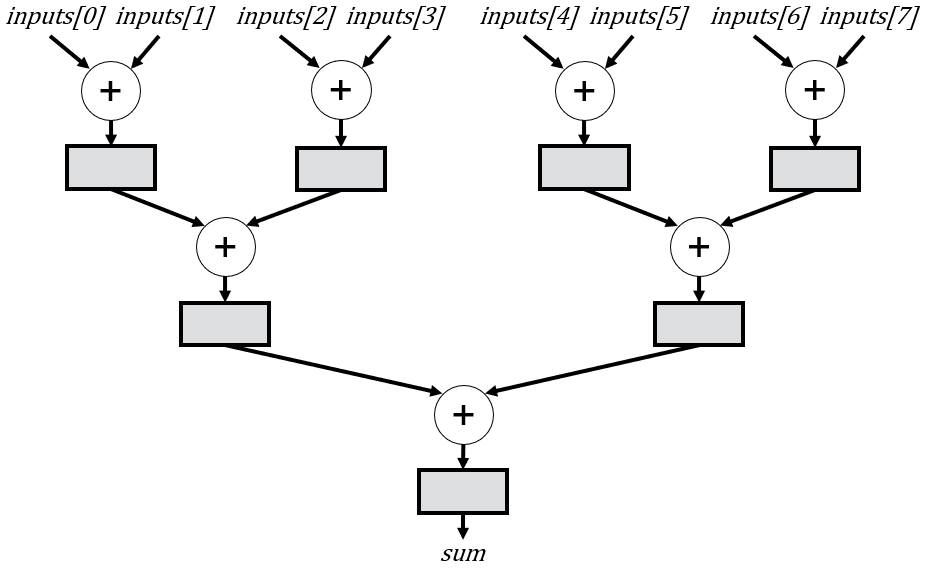
This example circuit is designed to process 8 inputs per cycle, delivering a sum every cycle with a 3-cycle delay. Such adder trees find widespread usage across various domains, including machine learning and digital signal processing. However, their input requirements can vary significantly, sometimes involving hundreds or even thousands of inputs per cycle. Hence, it’s imperative to develop a versatile module capable of accommodating these diverse use cases through parameter adjustments alone.
While it’s possible to implement a pipelined adder tree without recursion, the conventional methods I typically see in online examples often encounter issues or trigger numerous synthesis warnings. Moreover, when a tree necessitates intricate pipelining features—such as stage skipping or multiple registers in certain stages—achieving the desired functionality without recursion becomes increasingly challenging.
First, let’s take a look at the module we’ll be using:
// Greg Stitt, Christopher Crary
// StittHub (stitt-hub.com)

module add_tree
#(
    parameter int NUM_INPUTS=8,
    parameter int INPUT_WIDTH=16
) (
    input  logic                                      clk,
    input  logic                                      rst,
    input  logic                                      en,
    input  logic [                   INPUT_WIDTH-1:0] inputs[NUM_INPUTS],
    output logic [INPUT_WIDTH+$clog2(NUM_INPUTS)-1:0] sum
);
The module has two parameters: the number of inputs to add (NUM_INPUTS) and the bit width of each input (INPUT_WIDTH). The module takes an array of NUM_INPUTS inputs, where each input is INPUT_WIDTH bits. Subsequently, the module produces a sum whose width is determined as follows: at each level of the tree, the sum is extended with an additional bit to prevent overflow loss. Given that the depth of the tree is $clog2(NUM_INPUTS), the total width is calculated as INPUT_WIDTH + $clog2(NUM_INPUTS).
The elegance of recursion lies in the simplicity of the cases we need to consider. We first need to define “base cases”, which are instances that terminate the recursion. For example, the figure below shows several potential base cases (where n is equivalent to NUM_INPUTS). You will see shortly that we actually only need the base case for n = 1, but we show several here because other examples might require more cases. Also, in some situations you might want to specialize the implementation of certain base cases.
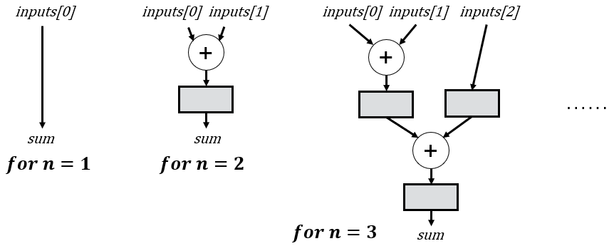
Notice that when dealing with just 1 input, we bypass the need for an adder altogether and directly assign the input to the output. You might question the rationale behind using an adder with a single input, and your confusion is understandable; indeed, we would never deliberately opt for this configuration. However, as we delve into subsequent cases, we’ll observe how all other recursive instances eventually lead to 1-input adder trees.
The corresponding code for the base case is shown below (this is part of a generate block). You might notice I also use $fatal to validate that NUM_INPUTS is positive. Some tools have pretty limited support for SystemVerilog parameter validation, so this might not work in your tool. However, it’s a good practice, so I included it for completeness.
if (NUM_INPUTS < 1) begin : l_num_inputs_validation
    // NOTE: $fatal might not be supported by all synthesis tools
    $fatal(1, "ERROR: Number of inputs must be positive.");
end else if (NUM_INPUTS == 1) begin : l_base_1_input
    assign sum = inputs[0];
end
For cases involving more than one input, the power of recursion becomes evident: we only require a single rule to address all scenarios. Specifically, with multiple inputs, we partition the tree into equal-sized left and right subtrees, subsequently summing the results of these subtrees to obtain our complete solution. The recursive definition inherently guides the implementation of these subtrees, adhering to the established rules. This concept is visually represented below in a schematic depiction, which we’ll leverage to construct a structural architecture. As a side note, it’s worth mentioning that there exists a more optimal method for splitting the inputs across subtrees, which we’ll explore in a future article.
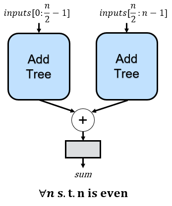
If we apply this rule multiple times, we eventually end up with the 8-input adder tree shown earlier, where every rounded rectangle is an instance of the recursive rule:
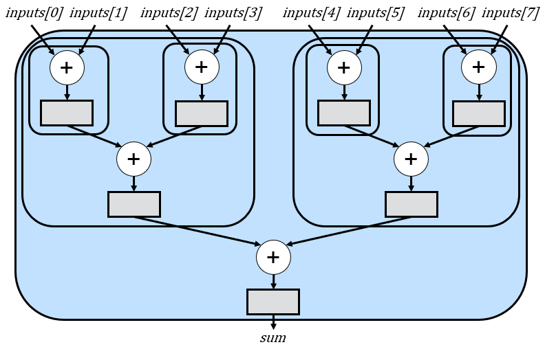
Basically, the first instance (with 8 inputs) adds two subtrees that each have 4 inputs. Those two subtrees add sub-subtrees that each add 2 inputs. If we use the base case for n=2, the recursion ends as shown. When only using one base case for n=1, there would also be recursive instantiations for just the inputs, which we omitted in the figure for simplicity.
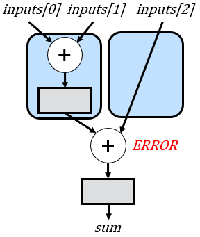
One problem with the strategy shown above is that if the number of inputs is odd, then the right subtree might have a different depth than the left subtree. While this discrepancy might not pose a concern in combinational logic, it becomes problematic in a pipelined architecture. The differing depths can lead to misalignment, causing one subtree to output its sum before the other. Consequently, this misalignment results in incorrect additions, as illustrated below for a scenario involving three inputs (this figure again includes a base case for n = 2 for simplicity):
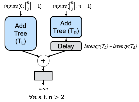
To address the misalignment issue, we can adjust the previous recursive rule. In cases where there is an odd number of inputs, we’ll allocate the extra input to the left subtree. Subsequently, we’ll compute the latencies of both the left and right subtrees based on their respective numbers of inputs and introduce delays to the right subtree if required. This adjustment ensures synchronization and prevents misalignments in the pipelined architecture.
If we apply these recursive rules to the 3-input example we saw earlier, we will now have the correct delay that aligns all additions:
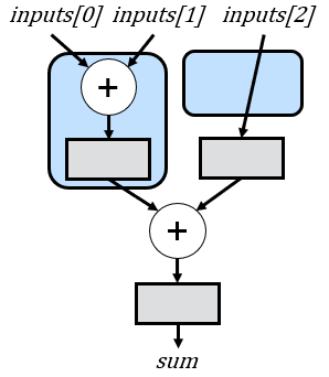
One nice feature of the strategy outlined above is that we don’t actually need separate rules for even and odd numbers of inputs. In cases where there are even inputs, the delay’s latency is simply 0 cycles (i.e., no delay). Although we only require a delay of 0 or 1 cycles due to the specific input splitting strategy across subtrees, I opt to maintain a more generalized approach to latency calculation. This ensures flexibility, especially in scenarios where modifications to the pipeline structure are introduced. For instance, if floating-point adds are employed, the latency between subtrees could vary significantly. Therefore, preserving a general latency calculation accommodates such potential variations in the pipeline design. In fact, in a future article, we’ll look at an improved strategy for splitting the subtrees that will require the more general delay, but will save delays overall.
We can now delve into coding this schematic. Similar to any other schematic, we can utilize a structural architecture. However, unlike non-recursive structural architectures, we will instantiate the module that we are currently defining (add_tree).
First, we instantiate the left subtree as shown below:
//--------------------------------------------------------------------
// Create the left subtree
//--------------------------------------------------------------------
// If your tool doesn't support $ceil, you can do: LEFT_TREE_INPUTS = NUM_INPUTS - NUM_INPUTS / 2;
localparam int LEFT_TREE_INPUTS = int'($ceil(NUM_INPUTS / 2.0));
localparam int LEFT_TREE_DEPTH = $clog2(LEFT_TREE_INPUTS);
logic [INPUT_WIDTH + $clog2(LEFT_TREE_INPUTS)-1:0] left_sum;

add_tree #(
    .NUM_INPUTS (LEFT_TREE_INPUTS),
    .INPUT_WIDTH(INPUT_WIDTH)
) left_tree (
    .clk   (clk),
    .rst   (rst),
    .en    (en),
    .inputs(inputs[0+:LEFT_TREE_INPUTS]),
    .sum   (left_sum)
);
Next, we similarly create the right subtree:
//--------------------------------------------------------------------
// Create the right subtree.
// The right subtree is smaller in the case that NUM_INPUTS is not even.
// As a result, its latency is shorter than the left subtree and must be
// aligned/delayed to ensure a correct pipeline.
//--------------------------------------------------------------------
localparam int RIGHT_TREE_INPUTS = NUM_INPUTS / 2;
localparam int RIGHT_TREE_DEPTH = $clog2(RIGHT_TREE_INPUTS);
logic [INPUT_WIDTH + $clog2(RIGHT_TREE_INPUTS)-1:0] right_sum, right_sum_unaligned;

add_tree #(
    .NUM_INPUTS (RIGHT_TREE_INPUTS),
    .INPUT_WIDTH(INPUT_WIDTH)
) right_tree (
    .clk   (clk),
    .rst   (rst),
    .en    (en),
    .inputs(inputs[LEFT_TREE_INPUTS+:RIGHT_TREE_INPUTS]),
    .sum   (right_sum_unaligned)
);
We now need to create the delay for the right subtree. There are various approaches we could take for this. Typically, I would utilize a separate delay module, which is one of my most frequently used modules. However, to streamline this example and avoid the need for multiple files, we’ll define the delay behaviorally, as demonstrated below:
//--------------------------------------------------------------------
// Delay the right sum so it is aligned with the left sum.
//
// For the current module, the LATENCY_DIFFERENCE will be either 0 or 1,
// but I'm leaving the general delay in case modifications are made.
// For example, floating-point adds, or just integer adds where not
// every level has a register, could require significantly different delays.
//--------------------------------------------------------------------

localparam int LATENCY_DIFFERENCE = LEFT_TREE_DEPTH - RIGHT_TREE_DEPTH;

if (LATENCY_DIFFERENCE > 0) begin : l_delay
    logic [$bits(right_sum)-1:0] delay_r[LATENCY_DIFFERENCE];

    always_ff @(posedge clk or posedge rst) begin
        if (rst) delay_r <= '{default: '0};
        else if (en) begin
            delay_r[0] <= right_sum_unaligned;
            for (int i = 1; i < LATENCY_DIFFERENCE; i++) begin
                delay_r[i] <= delay_r[i-1];
            end
        end
    end

    assign right_sum = delay_r[LATENCY_DIFFERENCE-1];
end else begin : l_no_delay
    assign right_sum = right_sum_unaligned;
end
Finally, we just add the subtrees and register the sum:
 // Add the two trees together.
always_ff @(posedge clk or posedge rst) begin
    if (rst) sum <= '0;
    else if (en) sum <= left_sum + right_sum;
end
We can now put all these components together to achieve a highly flexible adder tree capable of supporting any number of inputs while accommodating any input width.
// Greg Stitt, Christopher Crary
// StittHub (stitt-hub.com)

module add_tree
#(
    parameter int NUM_INPUTS=8,
    parameter int INPUT_WIDTH=16
) (
    input  logic                                      clk,
    input  logic                                      rst,
    input  logic                                      en,
    input  logic [                   INPUT_WIDTH-1:0] inputs[NUM_INPUTS],
    output logic [INPUT_WIDTH+$clog2(NUM_INPUTS)-1:0] sum
);
    generate
        if (INPUT_WIDTH < 1) begin : l_width_validation
            $fatal(1, "ERROR: INPUT_WIDTH must be positive.");
        end

        if (NUM_INPUTS < 1) begin : l_num_inputs_validation
            $fatal(1, "ERROR: Number of inputs must be positive.");
        end else if (NUM_INPUTS == 1) begin : l_base_1_input
            assign sum = inputs[0];
        end else begin : l_recurse

            //--------------------------------------------------------------------
            // Create the left subtree
            //--------------------------------------------------------------------
            // If your tool doesn't support $ceil, you can do: LEFT_TREE_INPUTS = NUM_INPUTS - NUM_INPUTS / 2;
            localparam int LEFT_TREE_INPUTS = int'($ceil(NUM_INPUTS / 2.0));
            localparam int LEFT_TREE_DEPTH = $clog2(LEFT_TREE_INPUTS);
            logic [INPUT_WIDTH + $clog2(LEFT_TREE_INPUTS)-1:0] left_sum;

            add_tree #(
                .NUM_INPUTS (LEFT_TREE_INPUTS),
                .INPUT_WIDTH(INPUT_WIDTH)
            ) left_tree (
                .clk   (clk),
                .rst   (rst),
                .en    (en),
                .inputs(inputs[0+:LEFT_TREE_INPUTS]),
                .sum   (left_sum)
            );

            //--------------------------------------------------------------------
            // Create the right subtree.
            // The right subtree is smaller in the case that NUM_INPUTS is not even.
            // As a result, its latency is shorter than the left subtree and must be
            // aligned/delayed to ensure a correct pipeline.
            //--------------------------------------------------------------------
            localparam int RIGHT_TREE_INPUTS = NUM_INPUTS / 2;
            localparam int RIGHT_TREE_DEPTH = $clog2(RIGHT_TREE_INPUTS);
            logic [INPUT_WIDTH + $clog2(RIGHT_TREE_INPUTS)-1:0] right_sum, right_sum_unaligned;

            add_tree #(
                .NUM_INPUTS (RIGHT_TREE_INPUTS),
                .INPUT_WIDTH(INPUT_WIDTH)
            ) right_tree (
                .clk   (clk),
                .rst   (rst),
                .en    (en),
                .inputs(inputs[LEFT_TREE_INPUTS+:RIGHT_TREE_INPUTS]),
                .sum   (right_sum_unaligned)
            );

            //--------------------------------------------------------------------
            // Delay the right sum so it is aligned with the left sum.
            // For the current module, the LATENCY_DIFFERENCE will be either 0 or 1,
            // but I'm leaving the general delay in case modifications are made.
            // For example, floating-point adds, or just integer adds where not
            // every level has a register, could require significant different delays.
            //--------------------------------------------------------------------
            localparam int LATENCY_DIFFERENCE = LEFT_TREE_DEPTH - RIGHT_TREE_DEPTH;

            if (LATENCY_DIFFERENCE > 0) begin : l_delay
                logic [$bits(right_sum)-1:0] delay_r[LATENCY_DIFFERENCE];

                always_ff @(posedge clk or posedge rst) begin
                    if (rst) delay_r <= '{default: '0};
                    else if (en) begin
                        delay_r[0] <= right_sum_unaligned;
                        for (int i = 1; i < LATENCY_DIFFERENCE; i++) begin
                            delay_r[i] <= delay_r[i-1];
                        end
                    end
                end

                assign right_sum = delay_r[LATENCY_DIFFERENCE-1];
            end else begin : l_no_delay
                assign right_sum = right_sum_unaligned;
            end

            // Add the two trees together.
            always_ff @(posedge clk or posedge rst) begin
                if (rst) sum <= '0;
                else if (en) sum <= left_sum + right_sum;
            end
        end
    endgenerate
endmodule
Reflections on Design Choices
I experimented with several versions of this code in an attempt to incorporate suggestions from my previous posts. These different versions are worth discussing as they may pose some confusion for readers due to seemingly conflicting advice. If you’ve read my article on reset coding styles, you’ll notice a small deviation from my advice there, which warrants explanation. Initially, I employed the suggested style of resetting signals at the end of the always block. However, I encountered a few issues with this approach when using an asynchronous reset. While this style functioned as hoped in Vivado, I encountered errors when using Quartus Prime Pro (side note: I rarely use Quartus Standard anymore due to its limited support for SystemVerilog). Changing the reset from asynchronous to synchronous fixed the errors in Quartus, but I deliberately opted for an asynchronous reset in this example. The rationale behind this choice was to ensure that when examining the design in a schematic viewer, the precise structure of the adder tree would be readily discernible. With a synchronous reset, some tools may depict multiplexers in the schematic to facilitate the reset, potentially leading to confusion when attempting to align the tool’s schematic with your own. Ultimately, since I was only assigning a single signal in each always block, the risk associated with resetting at the top of the block was minimal. Consequently, I concluded that it was the most suitable style for this particular example.
If you’ve read my timing optimization tutorials, you might also be puzzled as to why I included both a reset and an enable signal. In those tutorials, I advocate for resetting only signals necessary for correct execution. An adder tree output will rarely impact correctness after reset because it will simply be ignored until the outputs are valid. Similarly, I encourage the use of FIFOs to “absorb” stalls, rendering enable signals unnecessary. Interestingly, my inclusion of both reset and enable does not conflict with this advice. When designing a module, I often include these signals so they can be utilized in different use cases. If I don’t want to ever reset an instance of the adder tree, I’ll simply connect its reset to 1’b0 when I instantiate it, and the synthesis tool will optimize it away. Likewise, if I want to eliminate the need for an enable signal, I’ll just connect the enable port to 1’b1 during instantiation, and its fanout will disappear during synthesis. However, what happens if a situation arises where I need either the enable or the reset? In those cases, the module wouldn’t function properly if it didn’t provide those signals. Therefore, I include these signals to achieve the best of both worlds. The module now offers the flexibility of reset and enable, while still allowing for their optimization in specific instances.
Does Recursion Also Work in VHDL?
Yes, recursion in VHDL operates similarly to the SystemVerilog examples discussed above. However, I intentionally omitted the VHDL equivalent for the adder tree example, reserving it for a subsequent post comparing the usability of SystemVerilog and VHDL. In VHDL, arrays must be declared as a separate type, necessitating the creation of a separate package because the array is required in the port declaration for the inputs signal. Additionally, if you’re constrained to a tool that does not support the VHDL 2008 (or newer) standard, you cannot have an array of an unconstrained type. This limitation essentially means that we must resort to workarounds for using a parameter for the input width. While achievable, as we’ll explore later, this type of example is notably more convenient to implement in SystemVerilog.
Summary
In conclusion, embracing recursive RTL code offers a potent strategy that I strongly advocate for whenever feasible, particularly when defining problems in terms of smaller instances of themselves. Its application is especially advantageous for tree structures, which are very common in digital circuits. While a handful of tools may still exhibit issues with recursion, my experiences with recursive RTL designs span well over a decade across various tools. I encourage everyone to leverage the power of recursion in their RTL designs, as it undoubtedly enhances versatility.
